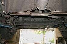
Twist-beam rear suspension


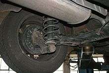
The twist-beam rear suspension (also torsion-beam axle or deformable torsion beam) is a type of automobile suspension based on a large H or C shaped member. The front of the H attaches to the body via rubber bushings, and the rear of the H carries each stub-axle assembly, on each side of the car. The cross beam of the H holds the two trailing arms together, and provides the roll stiffness of the suspension, by twisting as the two trailing arms move vertically, relative to each other.
About
The coil springs usually bear on a pad alongside the stub-axle. Often the shock is colinear with the spring, to form a coilover. This location gives them a very high motion ratio compared with most suspensions, which improves their performance, and reduces their weight.
The longitudinal location of the cross beam controls important parameters of the suspension's behaviour, such as the roll steer curve and toe and camber compliance. The closer the cross beam to the axle stubs the more the camber and toe changes under deflection. A key difference between the camber and toe changes of a twist beam vs independent suspension is the change in camber and toe is dependent on the position of the other wheel, not the car's chassis. In a traditional independent suspension the camber and toe are based on the position of the wheel relative to the body. If both wheels compress together their camber and toe will not change. Thus if both wheels started perpendicular to the road and car compressed together they will stay perpendicular to the road. The camber and toe changes are the result of one wheel being compressed relative to the other.[1]
-
Conceptual model of a twist beam suspension. The green segments illustrate the axle stub centerlines. At rest the axles are in line and the wheels are vertical (Camber = 0 degrees)
-
The twist beam suspension with the left axle deflected upwards. The deflected wheel now has negative camber. The left and right axles are no longer aligned. The right wheel's camber has changed to positive due to the deflection of the left wheel.
-
Single wheel deflection (deflection due to roll) vs both wheels up (deflection in bump). Note that when both wheels are deflected the axles remain in line and the wheels have no camber change.
-
Single wheel deflection shown vs both wheels at rest.
-
Both wheels shown deflected up (bump) and at rest. Note that the axle halves remain in line and the wheel camber does not change.
This suspension is commonly used on a wide variety of front wheel drive cars (mainly compacts and subcompacts), and was almost ubiquitous on European superminis. It was popularised by Volkswagen when they changed from rear engined RR layout cars in the 1970s, to front wheel drive FF layout cars.
This suspension is usually described as semi-independent, meaning that the two wheels can move relative to each other, but their motion is still somewhat inter-linked, to a greater extent than in a true independent rear suspension (IRS). This can mildly compromise the handling and ride quality of the vehicle. For this reason, some manufacturers have changed to different linkage designs. As an example, Volkswagen dropped the twist-beam in favour of a true IRS for the Volkswagen Golf Mk5, possibly in response to the Ford Focus' Control Blade rear suspension as well as the Hyundai Elantra (HD) or newer and Hyundai i30. General Motors in Europe Vauxhall/Opel have continued to use twist- or torsion- beam suspension. This is at a cost saving of €100 per car compared to multi-link rear suspension.[2] Their latest version as used in the 2009-on Opel Astra uses a Watts linkage at a cost of €20 to address the drawbacks and provide a competitive and cost effective rear suspension.[3] The Renault Megane and Citroen C4 also have stayed with the twist beam.[4] Toyota also switched from torsion beam to multilink with the 2007 Auris E150.
Advantages
- Low cost
- Can be durable
- Fewer bushings than multi-link suspension that are less stressed and less prone to wear
- Simple
- Neat package, reduces clutter under floor
- Fairly light weight
- Springs and shocks can be light and cheap
- No need for a separate anti-roll bar - the axle itself performs that function
Disadvantages
- Basic toe vs lateral force characteristic is oversteer
- Since toe characteristics may be unsuitable, adding toe-control bushings may be expensive.
- Camber characteristics are very limited.
- Not very easy to adjust roll stiffness
- Welds see a lot of fatigue, may need a lot of development
- Not much recession compliance - can be poor for impact harshness, and will cause unwelcome toe changes (steer effects)
- Wheel moves forward as it rises, can also be poor for impact harshness (this can be negated by designing the beam with the mounts higher than the stub axles, which impacts on the floorpan height, and causes more roll oversteer)
- Need to package room for exhaust and so on past the cross beam
- Camber compliance may be high
- No redress for wheel alignment. Alignment geometry is factory-set and not generally adjustable. Any deviation from factory specifications/tolerances could mean a bent axle or compromised mounting points.
References
- ↑ http://www.worldautosteel.org/uploaded/ULSAS_EngRpt_Twistbeam_Design.pdf
- ↑ http://www.richardaucock.com/astra-suspension-by-automotive-engineer/
- ↑ http://www.richardaucock.com/astra-suspension-by-automotive-engineer/
- ↑ http://ae-plus.com/focus/vehicle-dynamics-and-chassis-a-new-leaf