Volume and displacement indicators for an architectural structure
The volume (W) and displacement (Δ) indicators have been discovered by Philippe Samyn in 1997 to help the search for the optimal geometry of architectural structures.
The architectural structure
A resistant structure is anything amorphous or living, which supports the forces to which it is normally subjected without breaking.
Characterised by its shape and its constituent materials, and three-dimensional by nature, the amorphous structure usually has a two-dimensional geometry, which is given a thickness, or a three-dimensional geometry (the three-dimensional structure). The latter is formed of a pair of two-dimensional structures on non-parallel planes or three-dimensional curved volumes as in the case for any living things, including a specific group: the shells (a three-dimensional surface with a thickness). An example of these is the structure of cars, boats or planes, or even human skulls, sea shells or the stem of a dandelion.
The geometry of most "architectural" structures (such as buildings or bridges) is twodimensional and it is essential to study this aspect, whether for aesthetic, commodity-related or economic reasons. Several criteria are therefore taken into account in its definition.
Objective
The study is limited to the quest of the geometry giving the structure of minimum volume.
The cost of a structure depends on the nature and the quantity of the materials used as well as the tools and human resoures required for its production.
Although technological progress has reduced the cost of tools and the amount of human resources required, and despite the fact that computerised calculation tools can now be used to determine the dimension of a structure so that the load it bears at every point is within the admissible limits allowed by its constituent materials, it is also necessary for its geometry to be optimal. It is far from simple to find this optimal point because the choice available is so vast.
Furthermore, the resistance of the structure is not the only criterion to take into account. In many cases, it is also important to ensure that it will not undergo excessive deformation under static loads or that it does not vibrate to inconvenient or dangerous levels when subjected to dynamic loads.
Volume and displacement indocators, W and Δ, discovered by Philippe Samyn in August 1997, are useful tools in this regard. This approach does not take into account phenomena of elastic instability. Indeed, it can be shown that it is always possible to design a structure so that this effect becomes negligible.
The indicators
The objective is to ascertain the optimal morphology for a two-dimensional structure with constant thickness, which:
- fits in a rectangle of pre-determined dimensions, longitudinal L and horizontal H, expressed in metres (m);
- is made of one (or several) material(s) with a modulus of elasticity E, expressed in Pascals (Pa), and bearing a load at all points within its allowable stress(es) σ, expressed in Pascals (Pa);
- is resistant to the maximum loads to which it is subjected, in the form of a “resultant” F, expressed in Newtons (N).
Each form chosen corresponds to a volume of material V (in m³) and a maximum deformation δ (in m). Their calculation depends on the factors L, H, E, σ and F. These calculations are long and tedious, they cloud the objective of finding the optimal form.
It is, nevertheless, possible to overcome this problem by setting each factor to unity: while all other characteristics remain the same. Length L is therefore set to 1m, H to H/L, E and σ to 1Pa, and F to 1N. This "reduced" structure has a volume of material W= σV/ FL (the volume indicator) and a maximum deformation Δ = Eδ / σL (the displacement indicator). Their main characteristic is that they are numbers without physical dimensions (dimensionless) and their value, for every morphology considered, depends only on the ratio L/H, i.e. the geometric slenderness ratio of the form.
This method can easily be applied to three-dimensional structures as illustrated in the following examples.
The theory related to the indicators has been taught since 2000, and among other institutions, at the department of Civil Engineering and of Architecture at the Vrije Universiteit Brussel (VUB ; section "material mechanics and constructions") leading to research and publications under the direction of Prof. Dr. Ir. Philippe Samyn (from 2000 to 2006); Prof. Dr. Ir. Willy Patrick De Wilde (from 2000 to 2011) and now Prof. Dr. Ir. Lincy Pyl.
The "reference book",[1] since the reference thesis,[2] reports the developments of the theory at Samyn and Partners as well as the VUB, up to 2004.
The theory is open to everyone who wants to contribute, W and Δ being to be calculated for any resistant structure as defined in paragraph 1 here above.
Progresses in material sciences, robotics and three dimensional printing, lead to the creation of new structural forms lighter than anyone known today.
The geometry of minimal surfaces of constant thickness in a homogeneous material is, for example, substantially modified when thickness and/or local alloable stress are varying.
Macrostructure, structural element, microstructure and material
The macrostructures considered here may be composed of "structural elements" which material presents a "microstructure".
Whether searching to limit the stress or the deformation, macrostructure, structural element and microstructure have each, a weight Vρ, when ρ is the volumic weight of materials, in N/m³, function of the sollicitations {F0} (for "force" in général) applied to them, of their size {L0} (for length or "size" in general) , of their shape {Ge} (for geometry or "shape" in general), and of their constituting material {Ma} (for "material" in general).
It can also be expressed as shape and material ({Ge}{Ma}) defining the weight (Vρ) for the structure of a given size under given force ({F0}{L0}).

In material mechanics and for the structural elements under a specific loading case, the factor {Ge} corresponds to the "form factor" for elements of continuous section out of a solid material (without voids).
The constituting material might however present a microstructure with voids. This cellular structure enhances than the form factor, whatever the loading case.
The factor {Ma} caracterises a material which efficiency might be compared to another for a given loading case, and the independently of the form factor {Ge}.
The indicators W = σV/FL and Δ = δE/σL just defined, caracterise the macrostructures, while the same notations and symbols in small letters, w = σv/fl and Δ = δE/σl, refer to the structural element.
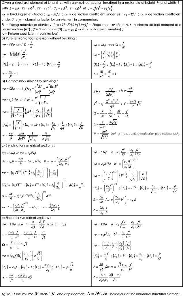
The figure 1 gives the values of W and Δ for the structural element subject to traction, compression, bending and shear. The left column relates to the limitation of stress and the right column to the limitation of deformation. It shows the direct relation of W to {Ge}{Ma} as:
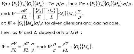
Which for a given loading case, is the specific weight of a macrostructure per unit of force and length, depending only from the geometry through L/H, and the materials though σ/ρ.
Wρ/σ includes thus, the material factor {Ma} (ρ/σ and ρ/E for tension and compression without buckling, ρ/E1/2 for compression limited by buckling, ρ/σ2/3 and ρ/E1/2 for pure bending, ρ√3/σ and ρ/G for pure shear) and the form factor {Ge}.
All other factor being equal, a cluster of tubes with a diameter H and a wall thickness e, compared to a solid bar of equal volume in a material caracterised by ρ , σ , E et G , presents an apparent density ρa = 4k(1-k)ρ with k=e/H, allowable stress σa = 4k(1-k)σ,

This explains the better performances of lighter materials for structural elements subject to compression or bending.
This indicator allows to compare the efficiency of macrostructures including geometry and material.
It echos the work of M.F. ASHBY: "Materials Selection in Mechanical Design" (1992).[3] He analyses {Ge} and {Ma} separately as, for his studies, {Ma} relates to a large amount of the materials physical propreties.
Different and complementary, it can also be placed alongside work carried out since 1969 by the INSTITUT FÜR LEICHTE FLÄCHENTRAGWERKE in Stuttgart under the direction of Frei OTTO and now Werner SOBEK, which refers to indices named Tra and Bic.[4] The Tra is defined as the product of the length of the trajectory of the force Fr, (causing the collapse of the structure) onto the supports by the intensity of this force, and the Bic is the relationship of the mass of the structure with Tra.
Since ρ* is the density of the material (in kg/m³), and α is, like W, a constant depending on the type of structure and the loading case:

Unlike W , which is dimensionless, Bic is expressed in kg/Nm. Therefore, depending on the material, an independent comparison of different morphologies is not possible. It is surprising to note that despite the abundance of their works, none of them mention or make any effort to study W and its relationship with L/H.
It appears that only V. QUINTAS RIPOLL[5],[6] and W. ZALEWSKI and St. KUS[7] mentioned the volume indicator W without examining it in depth.
Validity limits of W and Δ
- In general, the second order effects have very little influence on W, but they can have a significant impact on Δ. W and Δ therefore also depend on E/σ.
- The shearing force T may be crucial in the case of short and continuous elements, subject to bending so that W does not fall below a given value, regardless of the reduction of the slenderness L/H. However, this limitation is very theoretical because it is always possible to remove it by transferring material from the flanges to the web of the section, close to the supports.
- The stress σ to which the structure can be subjected depends on the nature, the internal geometry, the production method and the implementation of the materials, as well as several other factors, including the dimensional accuracy of the actual construction, the nature of the connections of the components or their fire resistance, but also the skill with which the geometry of the structure is designed to cope with elastic instability. Pierre Latteur,[8] who discovered the buckling indicator, studied the influence of elastic instability on W and Δ. In this regard, it is important to note that the existence of anchoring points of an element in traction may reduce the apparent permissible stress to the same level as the reduction necessary to take into account a moderate level of elastic instability. The influence on W of the buckling of the compressed parts on one side and of the anchoring points at the extremities of an element in traction on the other side is analysed on pages 30 to 58 in the « reference book ».
- The allowable stress σ is also often reduced by the need to limit the displacement δ of the structure since it is not possible to significantly alter E for a given material.
- Considerations regarding fatigue, ductility and dynamic forces also limit the working stress.
- It is not always straightforward to establish the nature and the overall maximum intensity of the forces F(including dead weight) to which the structure is subject, which again has a direct influence on the working stress.
- The connections of an element in compression or in traction are considered as hinged. Any clamping, even partial ones, introduce parasitic forces which add extra weight to the structure.
- For certain types of the structures, the volume of the connections adds to the net volume defined by W. Its importance depends on the nature of the material and the context in which it is used; this needs to be determined on a case-by-case basis. It follows that initially, only W and Δ should be taken into account for the morphological design of a structure, assuming that it is ultra-dampened (i.e. its internal damping is greater than the critical damping), which makes it impervious to dynamic stress. The volume V of a structure is therefore directly proportional to the total intensity of the force F which is applied to it, to its length L and to the morphological factor W; it is inversely proportional to the stress σ to which it can be subjected. Furhtermore, the weight of a structure is proportional to the density ρ of the material from which it is constructed. However, its maximum displacement δ remains proportional to the span L and the morphological factor Δ, as well as the ratio between its working stress σ and the modulus of elasticity E.
If it is a case of limiting the weight (or the volume) and the deformation of a structure for a given stress F and span L, with all other aspects remaining unchanged, then the work of the structural engineer involves minimalising W and ρ/σ on one side and Δ and σ/E ont the other.
Accuracy of W and Δ
Theoretical accuracy
For the large majority of compressed elements, it is possible to limit the reduction of the working stress to 25% by taking into account elastic instability, providing that the designer focuses on ensuring an efficient geometric design from as early as the initial sketches. This means that the increase in their volume indicator can also be limited to 25% . The volume of the elements subject to pure traction is also only very rarely limited to the product of the net distance over which a force is applied by a section strained at the permissible stress. In other words, their real volume indicator is thus also higher than the one which results from the calculation of W. A bar under traction can be welded at its extremities; no extra material apart from the negligible welding material is added, but the rigidity introduce parasitic moments which absorb some of the permissible stress.
The bar can be articulated at its extremities and work at its permissible stress, but this requires close end sockets or attachment mechanisms whose volume is far from negligible, especially if the bar is short or highly stressed. As L.H. COX demonstrated,[9] in this case, it is worth taking into account n bars each with a cross-section of Ω/n, strained by force F/n with 2n sockets, instead of one bar with a cross-section Ω strained by a force F with 2 sockets, since the total volume of 2n sockets in the first case is much less than that of 2 sockets in the second.
The anchoring of the extremities of a bar under traction can also be ensured by adherence, as is usually the case for the rebars in elements made of reinforced concrete. In this specific case, it is necessary to have an anchoring length at least 30 times the diameter of the bar. The bar then has a length L+60H for a useful length L; its theoretical volume indicator W = 1 becomes W = 1+60H/L. Consequently, L/H must be greater than 240 (which is always theoretically possible) so that W does not increase by more than 25%. This observation also helps to show another reason for taking into account n bars with a crosssection Ω/n instead of one bar with a cross-section Ω.
Finally, connections consisting of bolts, dowels, pins or nails, especially in the case of wooden components, significantly reduce usable sections. For elements in traction, a reduction of 25% in the working stress or an increase of 25% in the volume is therefore also necessary in the majority of cases. Determining the volume and the displacement of a structure using the indicators W and Δ is therefore reliable theoretically, providing that:
- the working stress is reduced by at least 25% ;
- de dessiner les éléments comprimés et les assemblages avec discernement.
- great attention is paid to the design of compressed parts and connections. The overall proportions of an optimised structure, without taking buckling into account, are significantly altered when the compressed bars need to be shortened to take account of elastic instability. It becomes sensitive to the scale effect, leading to an extension of the overall proportion and increasing the weight of the structure. Inversely, a shortening of the overall proportions is necessary when the volume of the connections needs to be considered, since the influence of this volume reduces when the bars are lengthened. This shows the advantage of accurately designing not only the compressed parts, but also the connections, in order to avoid these flaws. One of Niki de Saint-Phalle’s light sculptures are therefore preferable to Giacometti’s slender but heavy structures !
Practical accuracy
The volume of the material of the structure, as determined using W, can only be obtained accurately if the theoretical values of the relevant characteristic of the sections under strain σ can be measured in practice. As shown in figure 1 above, this characteristic is:
- Ω for an element under pure compression without buckling ;
- I for an element under pure compression with buckling (as well as for deformation under
pure bending) ;
- I/H for an element under simple bending.
It is always possible to obtain the precise value of these characteristics when the parts are made of moulded materials, such as reinforced concrete, or squared-off materials, such as wood or stone. However, this is not the case for laminated or extruded materials, produced on an industrial production line, such as steel or aluminium. It is important therefore to produce these elements with the smallest possible difference in size between two of them in order to avoid an unnecessary use of material. This use is consistent when the related deviation c between two successive values kn and kn+1 is constant, thus : (kn+1 - kn) / kn = c or kn+1 = (c+1) kn or kn+1 = (c+1)n k0.
This is the principle of the geometric series known as the Renard Series (named after Colonel Renard who was the first to use them in calculating the diameter of cabling on aircraft) featured in the French standard NF X01-002.[10] When all the necessary values are only very slightly greater than a series value, c represents the maximum increase and c/2 the average increase of W. Being universally used, the case of the steel profiles requires an in-depth examination (see the “reference book”; page 26 to 29). Consequently, the use of industrial steel profiles automatically leads to a significant increase of W :
- by half of the theoretical inaccuracy for pure compression ;
- pratically identical for bending or compression subject to buckling.
This situation is magnified when the number of profiles available is restricted, which may explain the use of forms which are not theoretically optimal but which tend to subject the available profiles to the permissible stress σ (such as, for example, pylons for high-voltage electric lines or variable height truss bridges). For structures subject to pure bending, this also explains the use of flate plates of variable lengths added to the flanges of these I profiles to obtain the inertia or resisting moment required, with the greatest degree of accuracy. Conversely, the significant variety in the tubes available enables a relative deviation value c which is both smaller and more constant. They also cover a much wider range in both the lower and higher characteristic values. Since their geometric performance is practically identical to that of the I profiles, tubes are the most appropriate industrial solution in order to practically eliminate any increase in the volume indicator W. Nevertheless, practical issues of availability and corrosion may limit their use.
Some examples of W and Δ
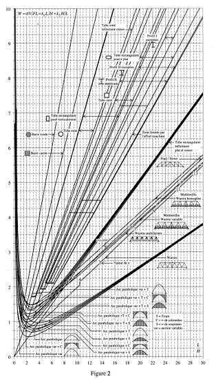
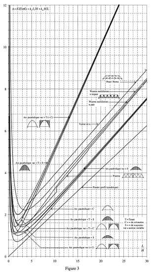
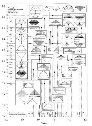
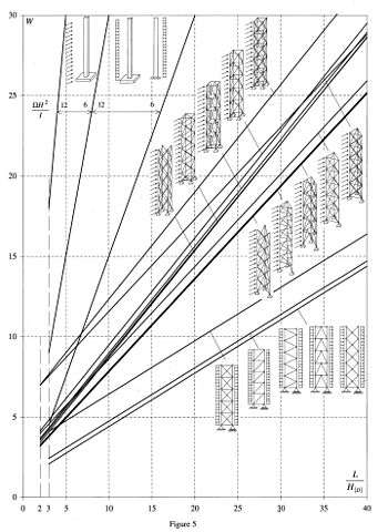
The following figures show the values of the indicators according to the ratio L/H for a number of types of structures.
figure 2 and 3 : W and Δ for a horizontal isostatic span under an uniformely distributed vertical load made up of:
- profiles with a constant cross-section, from I-section to solid cylinder;
- different types of trusses;
- parabolic arches with or without hangers or small columns, with constant or variable cross-sections.
figure 4 : for the transfer to two equidistant supports on the horizontal of a vertical point load (in this case Δ=W) or evenly distributed loead : F=1.
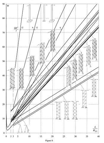
figure 5 and 6 : W for a vertical mast, with a constant width, subject to a horizontal load which is evenly distributed along its height or concentrated at the top.
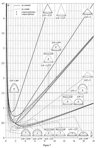
figure 7 : W for a membrane of revolution on a vertical axis, with a constant or variable thickness, under an evenly distributed vertical load. It is surprising to note that the minimum value is reached for a conical dome of variable thickness with an opening angle of 90° (L/H= 2 ; W= 0,5!).
Developments
Applications already discussed in the « reference book » are :
- trusses,
- straight continuous beams,
- arches, cables and guyed structures,
- masts,
- gantries,
- membranes of revolution.
Some examples of composite structures with minimum W
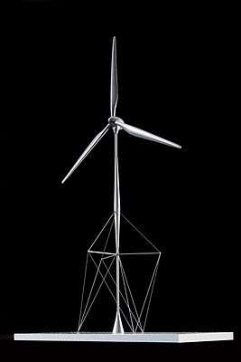
W can easily be determined in order to optimise structures made up of a number of different construction elements (see « reference book » page 100-106) as shown, for instance, for the wind turbine in figure 8.
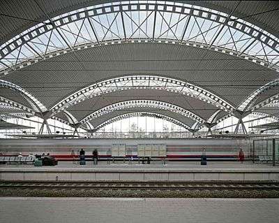
Or a parabolic roof coupled with large vertical glazed gables subject to wind loads, as seen at Leuven station in Belgium, shown in figure 9 (see reference[11] for a detailed analysis).
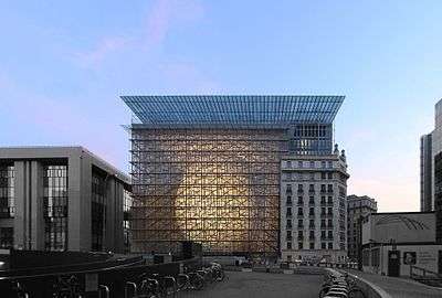
The optimisation of the King Cross truss for the facade of the Europa building in Brussels (see reference[12] page 93-101 for detailed analysis) is another example.
Notes and references
- ↑ Philippe SAMYN, Étude de la morphologie des structures à l’aide des indicateurs de volume et de déplacement, Académie royale de Belgique, Bruxelles, 2004, 482 p; www.samynandpartners.com (for online e-book), (ISBN 2-8031-0201-3).
- ↑ Philippe SAMYN, Étude comparée du volume et du déplacement de structures bidimensionnelles, sous charges verticales entre deux appuis vers un outil d'évaluation et de prédimensionnement des structures, Tome I : Mémoire, 175 p. ; Tome II : Annexes, 184 p. ; Tome III : Figures, 197 p. (4th of July 1999) ; Tome IV : Epilogue, 33 p. + 14 figures (1st of December 1999). PhD Thesis in Applied Sciences, University of Liège.
- ↑ M.F. ASHBY, Materials Selection in Mechanical Design, 311 pages, 1997. Butterworth-Heinemann edition, division of Reed Educational and Professional Publishing Ltd. Oxford (first edition in 1992 by Pergamon Press Ltd), UK.
- ↑ IL PUBLIKATIONEN : INSTITUT FÜR LEICHTE FLÄCHENTRAGWERKE, UNIVERSITÄT STUTTGART plaffenwaldring, 14, 70569 STUTTGART ; (Current director : Prof. Dr. Ir. Werner SOBEK). tel : 00.49.711.685.35.99 - fax :00.49.711.685.37.89
- ↑ Valentin Quintas RIPOLL, Pro. Titular Dep. Estructuras de Edificación E.T.S Arquitectura. Universidad Politécnica de Madrid, Sobre el teorema de Maxwell y la optimización de arcos de cubierta,Informes de la construcción, Vol 40, n°400, marzo/abril 1989, pages 57 à 70, Madrid.
- ↑ Valentin Quintas RIPOLL, Sobre las formas de minimo volumen de las celosías de sección constante, Informes de la Construcción, Vol 43, n°418, marzo/abril 1992, pages 61 à 77, Madrid.
- ↑ W. ZALEWSKI, St. KUS, Shaping structures for least Weight, proceedings of the I.A.S.S International Congress on Shells and Spatial Structures, Stuttgart, 1992, pages 376 à 383.
- ↑ P. LATTEUR, Optimisation des treillis, arcs, poutres et câbles sur base d'indicateurs morphologiques – Application aux structures soumises en partie ou en totalité au flambement, Tome I : Thesis, 328 p. ; Tome II : Thesis appendix, 12 p. ; Tome III : Appendix to chapter 2, 432 p. (May 2000). PhD Thesis in Applied Sciences, Vrije Universiteit Brussel.
- ↑ L. H. COX, The design of structures of least weight, 135 p., 1965, Pergamon Press, London.
- ↑ French National Association for Standardisation (Association Française de Normalisation/AFNOR), NFX 01-002 Guide pour le choix des séries de nombres normaux et des séries comportant des valeurs plus arrondies de nombres normaux, 6 pages, December 1967, Paris.
- ↑ Jan DE CONINCK, Leuven Railway Station, Waregem, Vision Publishers, 2008, 176 p., (ISBN 978-90-79881-00-0),(www.samynandpartners.com for online e-book
- ↑ Jean ATTALI, EUROPA, European Council and Council of the European Union, Lannoo-Racine, Tielt-Bruxelles, 2013, 256 p. (ISBN 978 940 1414494) (www.samynandpartners.com for online e-book)
