Traffic barrier

Traffic barriers (sometimes called crash barriers, or Armco barriers,[1] also known in North America as guardrails or guard rails[2] and in Britain as crash barriers[3]) keep vehicles within their roadway and prevent vehicles from colliding with dangerous obstacles such as boulders, buildings, walls or large storm drains. Traffic barriers are also installed at the roadside to prevent errant vehicles from traversing steep (non-recoverable) slopes or entering deep water. Traffic barriers are installed within medians of divided highways to prevent errant vehicles from entering the opposing carriageway of traffic and help to reduce head-on collisions. Some of these barriers, designed to be struck from either side, are called median barriers. Crash barriers can also be used to protect vulnerable areas like school yards, pedestrian zones or fuel tanks from errant vehicles.
While barriers are normally designed to minimize injury to vehicle occupants, injuries do occur in collisions with traffic barriers. They should only be installed where a collision with the barrier is likely to be less severe than a collision with the hazard behind it. Where possible, it is preferable to remove, relocate or modify a hazard, rather than shield it with a barrier.[4]
To make sure they are safe and effective, traffic barriers undergo extensive simulated and full scale crash testing before they are approved for general use. While crash testing cannot replicate every potential manner of impact, testing programs are designed to determine the performance limits of traffic barriers and provide an adequate level of protection to road users.[5]
Need and placement
Roadside hazards must be assessed for the danger they pose to traveling motorists based on size, shape and rigidity and distance from the edge of travelway. For instance, small roadside signs and some large signs (ground-mounted breakaway post) often do not merit roadside protection as the barrier itself may pose a greater threat to general health and well-being of the public than the obstacle it intends to protect. In many regions of the world, the concept of clear zone is taken into account when examining the distance of an obstacle or hazard from the edge of travelway.
Clear zone, also known as clear recovery area or horizontal clearance[6] is defined (through study) as a lateral distance in which a motorist on a recoverable slope may travel outside of the travelway and return their vehicle safely to the roadway. This distance is commonly determined as the 85th percentile in a study comparable to the method of determining speed limits on roadways through speed studies and varies based on the classification of a roadway. In order to provide for adequate safety in roadside conditions, hazardous elements such as fixed obstacles or steep slopes can be placed outside of the clear zone in order to reduce or eliminate the need for roadside protection.
- Common sites for installation of traffic barrier:
- Bridge ends
- Near steep slopes from roadway limits
- At drainage crossings or culverts where steep or vertical drops are present
- Near large signs/illumination poles or other roadside elements which may pose hazards
When barrier is needed, careful calculations are completed to determine length of need.[7] The calculations take into account the speed and volume of traffic volume using the road, the distance from the edge of travelway to the hazard, and the distance or offset from the edge of travelway to the barrier.
Barrier types and performance
Traffic barriers are categorized in two ways: by the function they serve, and by how much they deflect when a vehicle crashes into them.
Barrier functions

Roadside barriers are used to protect traffic from roadside obstacles or hazards, such as slopes steep enough to cause rollover crashes, fixed objects like bridge piers, and bodies of water. Roadside barriers can also be used with medians, to prevent vehicles from colliding with hazards within the median.
Median barriers are used to prevent vehicles from crossing over a median and striking an oncoming vehicle in a head-on crash. Unlike roadside barriers, they must be designed to be struck from either side.
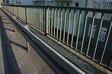
Bridge barrier is designed to restrain vehicles from crashing off the side of a bridge and falling onto the roadway, river or railroad below. It is usually higher than roadside barrier, to prevent trucks, buses, pedestrians and cyclists from vaulting or rolling over the barrier and falling over the side of the structure. Bridge rails are usually multi-rail tubular steel barriers or reinforced concrete parapets and barriers.
Work zone barriers are used to protect traffic from hazards in work zones. Their distinguishing feature is they can be relocated as conditions change in the road works. Two common types are used: temporary concrete barrier and water-filled barrier. The latter is composed of steel-reinforced plastic boxes that are put in place where needed, linked together to form a longitudinal barrier, then ballasted with water. These have an advantage in that they can be assembled without heavy lifting equipment, but they cannot be used in freezing weather.
Barrier stiffness
Barriers are divided into three groups, based on the amount they deflect when struck by a vehicle and the mechanism the barrier uses to resist the impact forces. In the United States, traffic barriers are tested and classified according to the AASHTO Manual for Assessing Safety Hardware (MASH) standards, which recently superseded Federal Highway Administration NCHRP Report 350. Barrier deflections listed below are results from crash tests with a 2,000 kg (4,400 lb) pickup truck traveling 100 km/h (62 mph), colliding with the rail at a 25 degree angle.[8]
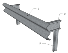
Flexible barriers include cable barriers and weak post corrugated guide rail systems. These are referred to as flexible barriers because they will deflect 1.6 to 2.6 m (5.2 to 8.5 ft) when struck by a typical passenger car or light truck. Impact energy is dissipated through tension in the rail elements, deformation of the rail elements, posts, soil and vehicle bodywork, and friction between the rail and vehicle.

Semi-rigid barriers include box beam guide rail, heavy post blocked out corrugated guide rail and thrie-beam guide rail. Thrie-beam is similar to corrugated rail, but it has three ridges instead of two. They deflect 3 to 6 feet (0.91 to 1.83 m): more than rigid barriers, but less than flexible barriers. Impact energy is dissipated through deformation of the rail elements, posts, soil and vehicle bodywork, and friction between the rail and vehicle. Box beam systems also spread the impact force over a number of posts due to the stiffness of the steel tube.

Rigid barriers are usually constructed of reinforced concrete. A permanent concrete barrier will only deflect a negligible amount when struck by a vehicle. Instead, the shape of a concrete barrier is designed to redirect a vehicle into a path parallel to the barrier. This means they can be used to protect traffic from hazards very close behind the barrier, and generally require very little maintenance. Impact energy is dissipated through redirection and deformation of the vehicle itself. Jersey barriers and F-shape barriers also lift the vehicle as the tires ride up on the angled lower section. For low-speed or low-angle impacts on these barriers, that may be sufficient to redirect the vehicle without damaging the bodywork. The disadvantage is there is a higher likelihood of rollover with a small car than the single slope or step barriers.[9] Impact forces are resisted by a combination of the rigidity and mass of the barrier. Deflection is usually negligible.
An early concrete barrier design was developed by the New Jersey State Highway Department. This led to the term Jersey barrier being used as a generic term, although technically it applies to a specific shape of concrete barrier. Other types include constant-slope barriers, concrete step barriers and F-shape barriers.
Concrete barriers usually have smooth finishes. At some impact angles, coarse finishes allow the drive wheel of front wheel drive vehicles to climb the barrier, potentially causing the vehicle to roll over. However, along parkways and other areas where aesthetics are considered important, reinforced concrete walls with stone veneers or faux stone finishes are sometimes used. These barrier walls usually have vertical faces to prevent vehicles from climbing the barrier.
Barrier end treatments
Early traffic barrier designs often paid little attention to the ends of the barriers, so they either ended abruptly in blunt ends, or sometimes featured some flaring of the edges away from the side of the barrier facing traffic. Vehicles that struck blunt ends at the wrong angle could stop too suddenly or have steel rail sections penetrate into the passenger compartment, resulting in severe injuries or fatalities.[10] As a result, a new style of barrier terminals were developed in the 1960s in which the installers were directed to twist the guardrail 90 degrees and bring its end down so that it would lie flat at ground level (so-called "turned-down" terminals). While this innovation prevented the rail from penetrating the vehicle, it could also vault a vehicle into the air or cause it to roll over, since the rising and twisting guardrail formed a ramp. These crashes often led to vehicles flying at high speed into the very objects which guardrails or barriers were supposed to protect them from in the first place.
To address the vaulting and rollover crashes, energy-absorbing terminals were developed. The first generation of these terminals in the 1970s were breakaway cable terminals, in which the rail curves back on itself and is connected to a cable that runs between the first and second posts (which are often breakaway posts). The second generation, in the 1990s and 2000s, feature a large steel impact head that engages the frame or bumper of the vehicle. The impact head is driven back along the guide rail, dissipating the vehicle's kinetic energy by bending or tearing the steel in the guide rail sections. A guide rail may also be terminated by curving it back to the point that the terminal is unlikely to be hit end-on, or, if possible, by embedding the end in a hillside or cut slope.

An alternative to energy absorbing barrier terminals are impact attenuators. These are used for wider hazards that can't be effectively protected with a one-sided traffic barrier.
Recycled tyres have been proposed for highway crash barriers, but most governments prefer sand-filled crash barriers because they have excellent absorption characteristics and are easier to erect and dismantle.[11]
A Fitch Barrier is a type of impact attenuator consisting of a sand-filled plastic barrels, usually yellow colored with a black lid.[12] Fitch barriers are often found in a triangular arrangement at the end of a guard rail between a highway and an exit lane (the area known as the gore), along the most probable line of impact. The barriers in front contain the least sand, with each successive barrel containing more, so that when a vehicle collides with the barrels they shatter, the kinetic energy is dissipated by scattering the sand and the vehicle decelerates smoothly instead of violently striking a solid obstruction, reducing the risk of injury to the occupants. Fitch barriers are widely popular due to their effectiveness, low cost, and ease of setup and repair or replacement.[13]
Types of end treatments:
- bull nose
- ET Plus
- Water and Sand Filled Barriers buffers
- Rubber end caps
- Quad guard crash cushion
- Pennsylvania Guardrail End Terminal
- Traffic barrier energy attenuator
- W-beam double buffer
See also
References
- ↑ AK Steel (formerly Armco) genericized trademark
- ↑ "Guardrail". Oxford Dictionary. Retrieved 7 September 2014.
- ↑ "crash barrier". Oxford Dictionaries Online. Retrieved 6 September 2015.
- ↑ "Barrier Need". TxDOT RDM. 2010-05-01. Retrieved 2011-01-11.
- ↑ Roadside Design Guide. American Association of State Highway Transportation Officials. 2002. pp. 1–3.
- ↑ "Cross Sectional Elements". TxDOT RDM. 2010-05-01. Retrieved 2011-01-11.
- ↑ "Determining Length of Need of Barrier". TxDOT RDM. 2010-05-01. Retrieved 2011-01-11.
- ↑ Roadside Design Guide, American Association of State Highway Transportation Officials, 2004, pages 5-10 to 5-23
- ↑ Frequently Asked Questions: Barriers, Terminals, Transitions, Attenuators, and Bridge Railings, Federal Highway Administration http://safety.fhwa.dot.gov/roadway_dept/policy_guide/road_hardware/qa_bttabr.cfm#brrs4 accessdate = 2/15/2011
- ↑ Roadside Design Guide, American Association of State Highway Transportation Officials, 2004, page 8-1
- ↑ "Markets for Scrap Tires" (PDF). Office of Solid Waste. EPA. Archived (PDF) from the original on 2012-07-10. Retrieved 2015-12-18.
- ↑ The Fitch Barrier
- ↑ Talk of the Morning: Time can't catch up with 86-year-old hot rodder.
